TEST FREQUENCIES

PHYSICAL COMPARISONS

TOUCH SCREEN

ADAPTER RANGE

MAINTENANCE
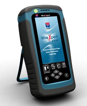
WireXpert
– Low cost for replacement
of PL test cords only
– Live and phone technical
support included
– Rugged industrial design
to reduce impact damage
– Low cost for replacement
of PL test cords only
– Live and phone technical
support included
– Rugged industrial design
to reduce impact damage
DSX-5000
– High cost to replace PL
test cords with adapter
– Only with Gold support
plan
– Fragile and delicate
parts may crack after
multiple impacts
– High cost to replace PL
test cords with adapter
– Only with Gold support
plan
– Fragile and delicate
parts may crack after
multiple impacts
PC SOFTWARE
eXport for WireXpert
ref: eXport v7.1.292
– No previous Certi ers
– Multilingual
– Supports *.PRX (native),
*.SOR (OTDR)
– Exports to *.PDF, *.CSV
– Exports to compressed
*.PDF les for small le size
– Supports inverted Y-axis
plots
– Supports re-certi cation
– Supports cable pairing
conversion between
T568A and T568B
– Supports remote display
for presentation purposes
– Generates customisable
hierachical based labels
for list based testing
(Bld/Fl/Tel/Rk/Pn/Prt)
– Generates labels for
point-to-point for
connections
(eg. a1/b2 to a5/b5)
LinkWare for DSX-5000
ref: LinkWare 9.3
– Backward compatible to
previous Analyzers
– Multilingual
– Supports *.FLW (native),
*.TST (native)
– Exports to *.PDF, *.CSV,
*.TXT, *.XML
– Does not compress
*.PDF le
– Does not support
inverted Y-axis plots
– Supports re-certi cation
– Does not support
conversion
– Does not support
remote display
– Generates basic
sequencial labels
(eg. a1-b5)