Category: Uncategorized

Network Cabling Tidy Up

spaghetti network

If you are supporting this network, how you think about this?

Simple question : Where do i start for making this look better?

Advance question(answer if in the mood) : tools and practices to map it from the beggining and document the mappings.

Reason #1: To Maintain Efficiency

The more disorganized the telecom cables are, the harder it is to make changes, troubleshoot problems, and upgrade equipment. If patch cables are a tangled mess and hanging in front of equipment, then accessing the equipment is much more difficult when something needs to be added or repaired. It also makes things more difficult in case a workstation cable needs to be troubleshot or new cables need to be added to the telecom room. All of this just wastes time and resources that could be better spent on tasks that are more critical to the organization.

Reason #2: To Improve Network Performance and Stability

The messier the data cables are, the more likely it is that equipment connections can become loose, disconnected or damaged when performing routine maintenance. It is also likely that some of the cables and connections are of poor quality, which can contribute to network outages or decreased performance.

A dangling mess of cables in front of equipment can also impede the circulation of air and cause switches, servers, or other active equipment to work harder and potentially overheat.

Furthermore, when performing moves, adds, and changes (MAC) work, having messy and disorganized data cables increases the risk of someone mistakenly disconnecting or even causing permanent damage to a vital piece of equipment.

Let’s face it, most people don’t really care until they start to feel the impacts themselves—in the form of slower e`mail, garbled phone conversations, intermittent or unplanned network outages, or slow Internet. Each of these things are a nuisance at best—but for most organizations, it could severely impact employee productivity and affect the bottom line. For other organizations, such as financial institutions and hospitals, these outages could pose a more serious threat and have a significant impact on the people those organizations serve.

Reason #3: To Reduce the Risk of Electrical Fire

In a messy, disorganized telecom room, electrical connections to active equipment will likely be a similar mess. It’s a rare case when the network patch cables are a complete mess but the power cords are properly organized and connected. The “daisy-chaining” of extension cords and power strips can easily overload an electrical outlet, which in extreme cases could cause electrical sparking or overheating that may ignite a fire.

Performing a telecom room cleanup will help reveal improperly-connected power cords and allow for the proper distribution of power to critical equipment—reducing the risk of fires and accidental power outages.

Reason #4: To Maintain a Professional Appearance

Appearances matter to employees, customers, and visitors—a clean, tidy, and organized space provides a positive impression at every level. For this reason, much attention is given to the design and layout of the overall office space, furnishings and especially the reception area.

A clean work area is one that employees can be proud of and be more inclined to take extra care to keep neat and organized. It also projects a professional image for visiting clients or other guests.

Although most clients, visitors and even employees may not see or be exposed to the telecom room, the same principles apply. A messy and disorganized telecom room can be misunderstood as being a reflection of the entire organization and could impact the organization’s ability to recruit or retain qualified IT personnel.

A side benefit of cleaning up telecom room cabling is that it makes things much easier to clean and maintain—which helps improve the appearance, performance and reduce fire hazards.

Rack Smart PDU PX3-1842V

PX3 1842V front

Features

  • Securelock
  • Removable Controller
Energy Metering

Voltage (V), Current (A), Active Power (kW), Real Power (kVA), Energy (kWh), Power Factor

Metering Accuracy

ISO/IEC 62053-21 1%

Remote Outlet Switching

No

Metering per input line

Yes for all models

Metering per Branch Circuit Breaker

Yes

Environmental Sensor Ready

Yes

Compatible Sensors

Temperature, Humidity, Air Flow, Differential Pressure, Water Leak, and Contact Closure.

View all sensors.

Cascading

Yes, Max 8 PDUs can be daisy chained using a single Ethernet connection

Networking

10/100/1000 BaseT Ethernet. Optional WiFi (802.11a/b/g/n)

Onboard Display

Color, matrix LCD display : Voltage, current, or active power (per line or per breaker); Alarms; Configuration information (name, ratings, IP / Networking information). Auto-flip orientation

Specifications

Input

Input Plug

IEC 60309 2P+E 6h 32A (2P3W)

Nominal Voltage

230V

Maximum Input Current

32A

Rated Input Current

32A

Power Capacity

7.4kVA

Cord Length

3m


Output

Nominal Voltage

230V

Receptacles (Output Connections)

(24) IEC320 C13

(6) IEC320 C19

Overload Protection

(2) LEGBXA6-16


Physical

Dimensions (WxDxH)

2.1in x 2.2in x 70.1in; 52mm x 55mm x 1780mm

Unit Weight

6.2 kg

Shipping Weight

8.4 kg

Shipping Dimensions

280mm x 115mm x 2055mm

Mounting

Tool-less Button Mount


Environmental

Operating Temperature/Environment

60 C

Operating Relative Humidity

85%

Operating Elevation

0-10000ft


Conformance

Regulatory Approvals

CE

Warranty

Standard 2 years manufacturer warranty

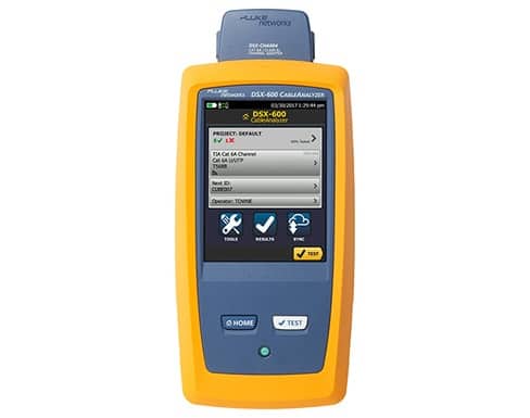
DSX-600 CableAnalyzer

17103 Fn dsx 600 EN ENGLISH 01a cMAIN

Essential certification of copper, twisted pair structured cabling from Cat 3 / Class C through Cat 6A / Class EA

The DSX-600 from Fluke Networks provides essential Cat 6A and Class EA Copper Certification featuring ten second test times and advanced user interface. Manage jobs and testers from any smart device over Wi-Fi with LinkWare™ Live. Features legendary Fluke Networks reliability backed by worldwide support.

  • Cat 6A and Class EA Copper Certification
  • Includes Channel Measurement Adapters; Optional rugged Permanent Link Adapters with removable test plug available
  • 10 second Cat 6A test time
  • ProjX™ Management System makes test setup fast and foolproof
  • HDTDX and HDTDR diagnostics pinpoint fault location
  • Integrates with LinkWare™ Live to manage jobs and testers from any smart device.
  • Quickly and easily create professional custom PDF reports with LinkWare™ PC.

Unique Features

  • The DSX-600 enables users to accomplish more than ever before by accelerating every step of the testing process
  • LinkWare Live cloud service lets the Project Manager remotely set up the testers, monitor job progress and even location from any smart device
  • ProjX™ management system eases tasks from initial set-up of a job to system acceptance. It eliminates redundant steps, and ensures that all tests are completed correctly the first time, and every time
  • Taptive™ user interface puts advanced data analysis and easy set-up and operation at the fingertips of technicians of all skill levels
  • LinkWare PC management software provides unmatched analysis of test results and professional test reports

Standards

  • TIA – Category 3, 5, 5e, 6, 6A per TIA 568-C.2 or TIA-1005
  • ISO/IEC – Class C and D, E, EA certification per ISO/IEC 11801:2002 and amendments
  • IEEE 802.3 – 10BASE-T, 100BASE-TX, 1000BASE-T, 10GBASE-T

Performance

  • Nine second Cat 6/Class E and 10 second Cat 6A/Class EA test time contributes to the fastest way to gain certification
  • Graphically displays the source of failures, the DSX-600 HDTDR and HDTDX algorithms provide quick, easy-to-understand directions to identify the point of failure (distance from the tester).
  • Manage up to 12,000 Cat 6A test results with full graphics
  • Capacitive touchscreen allows quick tester setup with easily selectable cable types, standards and testing parameters

ProjX™ Management System Manages Complex Jobs with Ease

Manage up to 12,000 Cat 6A test results with full graphics

Managing the testing of multiple jobs with multiple teams, testers, and requirements is time consuming and a source of errors. Increasingly larger jobs make project organization more important than ever. The new ProjX management system on the DSX-600 CableAnalyzer provides individual project files for all job specific details to be saved under a simple name, eliminating the need to re-enter job specific details after starting a project. This minimizes set-up errors or lost files when switching from one job to another or utilizing multiple testers on a single job. In addition, it provides test results by cable ID, merges any changes without duplicates and defaults to the last copper or fiber module installed. ProjX management system provides real time status to completion on each job with a 0-100% scale and gives the operator the option to isolate any test requiring a second look and helps to assure nothing is overlooked. The “Fix Later” selection creates a punch list or automatic to do list for correcting any workmanship issues. ProjX enables project managers and crew leaders to be truly efficient.

Performs with Unsurpassed Speed

Ten second Cat 6A test time and the fastest way to submit your certification results

No tester offers so much speed for so many tests. Complete copper certification to Cat 6A in 10 seconds . Quickly get a Pass or Fail result and easily review individual test parameters by value or drill into specific area on a graph.

LinkWare™ PC Cable Test Management Software

Leveraging the popular and multi-featured LinkWare PC management software application, DSX-600 users can easily access the ProjX management system data, generate reports, and upgrade the software in their testers. Project Managers have full capabilities to manage workflow and consolidate test results. Users can provide the finishing touch by adding their company logo to the report and offer it unaltered to their customers for system acceptance purposes. Keep your business tools simple, no matter which Fluke Networks copper or fiber tester you are using, LinkWare PC is the software package that reports it all.

Now with LinkWare PC stats, the new automated statistical report option, you can move above and beyond the page-per-link report and see your entire cabling infrastructure. It analyzes and transforms LinkWare PC test results data into charts and diagrams that reveal your cabling plant performance; this report summarizes your entire cabling infrastructure in a compact, graphical format that makes it easy to verify margins and to spot anomalies.

LinkWare™ Live Test Results Management Service

LinkWare Live is a cloud-based service that lets you manage certification jobs anytime, anywhere, with anyone on any device.  With LinkWare Live, you can:

  • Keep track of every test on every job. Get an overview of every project from any smart device. Drill down to each individual test. Instantly receive notification of incorrect test setting or cable IDs.
  • Get it right the first time. Define cable IDs and test settings from your PC or tablet.
  • Keep your testers up to date. Standards can change without notice, and an out-of-date test report can mean hours of re-testing. LinkWare Live automatically ensures your testers are running the latest.
  • Stop wasting time and gas driving testers back to the office. Upload your test results straight from the job site to LinkWare Live over Wi-Fi. Then download them automatically to the right job for fast report generation with LinkWare PC.
  • Avoid Project Delays. Track the last used location and monitor the status of all testers to ensure they are always calibrated and running the latest firmware*


Network Cabling Site Survey Check List

1 Information sources
Information for this document can be collected from the following sources:
· Customer’s representative
· Site survey
· Available documents and architectural drawings (see below)
· Local authorities, having jurisdiction
· Other subcontractors
2 Recommendations
· Never believe or assume, always check
· Collect all data from the customer in written form
· Use the latest version of your vendor’s Design Manual
· Use BICSI TDMM manual
· Use cabling standards

3 Customer Documentation
Request that the customer provides all or some of the following documents and drawings:
· Site plan
· Floor plans
· Elevation plans
· Roof plans
· Reflected ceiling plans with light fixture locations
· Power plans with possible EMI sources
· Outlet location plans
· Mechanical plan with HVAC duct locations
· Sprinkler plan with sprinkler pipe locations
3.1.1.1 Site plan
· Is it available?
· Does it contain property lines, building outlines, water and gas pipe lines, power lines
(aerial/buried/underground), trees, roads, other obstacles?

4 Applications Considerations
4.1.1 Horizontal Applications
· What services are to be provided to work areas (voice, data, video, other)?
· What are the requirements of each service per work area (number of copper pairs per
application, number of fibers per application)?
4.1.2 Intrabuilding Backbone Applications
· What services are to be supported by the backbone cabling (voice, data, video, other)?
· What are the requirements of each service (number of copper pairs per application,
number of fibers per application)?
4.1.3 Campus Applications
· What services are to be supported by the backbone cabling (voice, data, video, other)?
· What are the requirements of each service (number of copper pairs per application,
number of fibers per application)?

5 Architectural Considerations
· Equipment Room (ER)
· Telecommunications Closets (TC)
· Backbone Pathways
· Horizontal Pathways
· Entrance Facility
· Grounding and Bonding System
5.1 Equipment Room
5.1.1 Location
· Identify desirable ER location of the equipment room on the site plan
Size
· Height and width
· Usable floor space
· Usable wall space
· Ceiling height
· Power feeder location
5.1.2 Served Systems
· What equipment is to be placed in the equipment room?
· Identify type, size, weight and manufacturer’s installation requirements
5.1.2.1 Mounting of Connecting Hardware
· Identify the preferred method of mounting the connecting hardware (wall-mount, rackmount,
cabinets)
5.1.2.2 Mounting of Active Equipment
· Identify the preferred method of mounting the active equipment (wall-mount, rack-mount,
cabinets)
5.1.3 Approved Grounding
· Is it available?
· Mark location on the site plan
5.1.4 Means of bringing in heavy equipment available?
· Elevator rating
· Elevator door size
5.1.5 Floor-loading capacity
· Check that floor-loading capacity is adequate for heavy equipment which will be placed in
the equipment room.

5.1.6 Climate control system
· Is it available?
· What type (dedicated/non-dedicated)?
· Humidity control available?
· Temperature control available?
· Dust and contaminant control available?
· Is climate control system operation continuous?
5.1.7 Fire-extinguishing system
· Is it available?
· What type?
· Fire extinguishers available?
· If needed, consult local fire inspector
5.1.8 Firestopping
· Locate fire barriers, check their ratings
· Locate possible penetrations in fire barriers that may require firestopping
· If needed, consult local fire inspector
5.1.9 Lighting system
· Is it available?
· What capacity?
· Is it adequate?
· Is emergency lighting needed?
5.1.10 Possible EMI sources
· Location
· Type
· Mark EMI sources on the site plan
5.1.10.1 Possible hazards
· Locate any sources of water flooding, seepage, steam, heat, corrosive atmosphere
· Mark them on site plan
· Is the equipment room located above any threat of flooding?
5.1.11 Electric Power
· Number and location (mark on the equipment room plan)
· Is it adequate?
· Is power quality adequate for operating electronic equipment?
· Is emergency power system available?
· If needed, consult the electric power subcontractor
5.1.12 Plywood wall covering
· Is it available (in case of wall-mounting)?
· Is it void-free and fire-rated or coated with at least two coats of fire-resistant paint?
· How reliable is its mounting?

5.1.13 Access and proximity to entrance facility
· Locate entrance facility and determine distance and available pathways to the equipment
room
· Mark entrance facility location on the floor plan
5.1.14 Access to Backbone Pathways
· Identify and mark the location and size of backbone pathways on the equipment room plan
5.1.15 Space for internal cable pathways inside equipment room
· Is it available?
· What are customer preferences (cable trays, access floor)?
5.1.16 Dust and Static Electricity
· The floor surface must not produce dust and static electricity.
· What type of floor surface is present?
· Is it adequate?
5.1.17 Doors
· Is the door fully-opening or removable?
· Is the door lockable?
· What size (width, height)?
The size must be appropriate for bringing in the hardware and equipment.
5.1.18 Security
· What security means are available?
· What are customer requirements?
· Does any other building service pretend to share ER?

5.2 Telecommunication Closet
This step must be repeated for every telecommunications closet in the building.
5.2.1 Type and Location
· Identify and discuss possible location of the telecommunications closet on the floor plan
· Identify and discuss its type (cabinet/shallow closer/enclosed closet)
· Check if the telecommunications closet is accessible from a hallway or other common area
5.2.2 Floor Space Served
· Identify the usable floor space served by the telecommunications closet
· Identify the work areas served by the telecommunications closet
Size
· Length and width
· Usable floor space
· Usable wall space
· Ceiling height
5.2.3 Access to Backbone Pathways
· Identify and mark the location and size of backbone pathways on the telecommunications
closet plan
5.2.3.1 Mounting of Connecting Hardware
· Identify the preferred method of mounting the connecting hardware (wall-mount, rackmount,
cabinets)
5.2.3.2 Mounting of Active Equipment
· Identify the preferred method of mounting the active equipment (wall-mount, rack-mount,
cabinets)
5.2.4 Sharing with other services
· Check if equipment/hardware not related to the telecommunications and its support is
located or pass through the telecommunications closet. The telecommunications closet
may not be shared with services that interfere with telecommunications services.
5.2.5 Horizontal cable length
· Check if location of TC is within the limit of the allowed horizontal cable length
5.2.6 Doors
· Is the door fully-opening or removable?
· Is the door lockable?
· What size (width, height)?
The door size must be appropriate for bringing in the hardware and equipment.
5.2.7 Dust and Static Electricity
· The floor surface must not produce dust and static electricity.
· What type of floor surface is present?
5.2.7.1 Served Systems
· Will the telecommunications closet contain active equipment?
5.2.8 Floor-loading capacity
· Check that floor-loading capacity is adequate.
5.2.9 Future expansions
· Determine customer’s future expansion needs

5.3 Backbone Pathways
· Is it available?
· What type ? (sleeve, slot, conduit, cable racks)
· What size and quantity?
· Location?
· What is the total floor space served by backbone pathways?
· Are vertical shafts available?
· Are they vertically aligned?
· Are they connected to Equipment Rooms and Telecommunications Closets?
· What size and location ?
5.3.1 Firestopping
· Locate building fire barriers and check its ratings.

5.4 Horizontal Pathways
· Are they available?
· What type and size?
· If present, check the fill ratio. What cable is already placed in the pathways?
· Customer preferences?
· Determine the location of EMI sources in spatial relation to the horizontal pathways
· Determine the location of HVAC pathways in spatial relation to the horizontal pathways
· Determine the location of sprinkler pipes in spatial relation to the horizontal pathways
· Check side and top clearances of installed pathways

5.5 Entrance Facility
· Mark location on the floor plan
· Type (underground, buried, aerial)
· Locate the equipment room and determine distance and available pathways to the
entrance facility
· Check if a grounding busbar in the close proximity to entrance facility is available

5.6 Grounding and Bonding System
· Is a separate telecommunications grounding and bonding system available?
· If yes, is it compliant to TIA 607?

6 Horizontal Cabling Subsystem
This step must be repeated for each floor/Telecommunications Closet
· Determine usable floor space
· Determine number and location of Work Areas (mark on the site plan)
· Determine number, type (copper, fiber) and mounting of Telecommunications Outlets per
work area (mark on the site plan)
· Determine needed type of horizontal cable (copper, fiber)
· Determine cabling method (home-run, zone wiring)
· Mark the location of serving Telecommunications Closet

7 Building Backbone Cabling Subsystem
This step must be repeated for each Telecommunications Closet and for each type of backbone
cabling (copper voice; copper data; fiber data).
· Backbone cabling type (copper, fiber)
For copper cable: performance category, total number of pairs, number of pairs per cable
and number of cables
For fiber cable: total fiber count, type (multimode/single-mode), number of fibers per cable
and number of cables
· Number of work areas served by backbone
· Backbone redundancy needed?
· Backbone cabling pathways (see “Architectural Considerations”). Are they adequate?

Cat5 vs Cat5e vs Cat6 – Which Should You Use?

Cat5 vs Cat5e

  • Network support – CAT 5 cable will support 10BASE-T and 100BASE-T network standards, that is it supports networks running at 10 Mbps or 100 Mbps.  CAT 5e is an enhanced version of Cat5 that adds specifications for crosstalk (see below). Cat5e cable is completely backwards compatible with Cat5, and can be used in any application in which you would normally use Cat5 cable. However, the added specifications of Cat5e enable it to support Gigabit Ethernet (1000BASE-T), or networks running at 1000 Mbps.
  • Crosstalk – Crosstalk is the “bleeding” of signals between one cable into another, due to a process called induction. This effect can result in slow network transfer speeds, and can even completely block the transfer of signals over the cable. Cat5e cable has been improved over Cat5 cable in this respect, and crosstalk has been greatly reduced.
  • Bandwidth – The bandwidth of a given conveyance media is essentially it’s information carrying capacity. The greater the bandwidth of a system, the faster it is able to push data across a network. Cat5 is rated at 100Mhz while Cat5e is rated at 350Mhz. This coupled with other more stringent specifications makes Cat5e ideally suited for networks which plan to operate at Gigabit Ethernet speeds.
  • Bottom Line: If you plan on to implement Gigabit Ethernet, go with Cat5e. Also, the small increase in price of Cat5e over Cat5 is more than made up for by “future proofing” your network’s cabling infrastructure.


Cat5e vs Cat6

There is a great deal of debate among people about whether new cabling installations should use Cat5e or Cat6. Many people incorrectly assume that by running Cat6 they will then have a Gigabit Ethernet. However, in order to achieve true Gigabit Ethernet speeds, every single component on a network must be gigabit rated, such as the switches, hubs and network interface cards. This isn’t to say that there aren’t differences between Cat5e and Cat6, however. The general difference between category 5e and category 6 is in the transmission performance. While Cat5e can support gigabit speeds, Cat6 is certified to handle gigabit Ethernet. Additionally, the Cat6 specification is better suited toward environments that are generally unfriendly to twisted pair cabling. This includes areas that have lots of interference from things like power lines, lights, and manufacturing equipment. Still, for most applications, Cat5e is perfectly suitable and preferable to Cat6: it is more economical and performs almost as well. However, if you can be certain that all the components on your network are gigabit rated, and the volume of the data being transmitted calls for certified gigabit performance, then Cat6 is the way to go.


reference: www.networkcablingdirectory.com/articles/structured-network-cabling-id_1151.htm

Structured Cabling – Proper Way

Structured Cabling vs Conventional Point-to-Point Cabling

What is structured cabling?

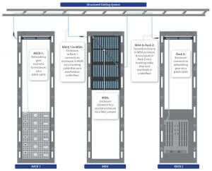
Structured Cabling… is defined as building or campus telecommunications cabling infrastructure that consists of a number of standardized smaller elements (structured).

A properly designed and installed structured cabling system provides a cabling infrastructure that delivers predictable performance as well as has the flexibility to accommodate moves, adds and changes; maximizes system availability, provides redundancy; and future proofs the usability of the cabling system.

– as defined on CABLExpress.com cabling glossary

Structured Cabling Solution

structured cabling

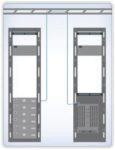
Point-to-Point Cabling (Conventional Structured Cabling System)

point to point

What is the benefit of structured cabling system

What Are the Benefits of Structured Cabling?

Once again, organization is the key word here. With an organized structured cabling system the benefits are:

MAC’s are much quicker due to the fact that they are done in the MDA versus running long patch cords from equipment racks.
Potential for downtime is reduced as potential for human error is drastically reduced due to this organization.
Time savings: cable and port tracing becomes a much easier job with a structured cabling system.
Aesthetics: Never underestimate the looks! A structured cabling system will look much cleaner than a point to point method. Since the changes are done in the MDA versus at the hardware, the hardware can be cabled up and not touched in most instances. This allows the cabling in front of the switch to remain aesthetically pleasing.

What are Risk staying with conventional structured cabling system

Downtime!

With an unorganized messy cabling infrastructure, mistakes are commonly made. Incorrect ports are unplugged. Even worse is the messy cabling that gets in the way. Trying to remove a single cable from a large tangled mess can cause stress on the other cables. This stress can lead to network and channel errors in the hardware that are very difficult to trace.

Airflow: If a point to point method is used, the front and potentially the sides of the switch are congested with cabling bulk. This impedes the airflow that the switch needs to operate. This also translates to underfloor cooling; cabling congestion in this space hinders the airflow of the CRAC unit and can cause cooling issues.