Category: Info

Fusion or Mechanical: Which Is the Best Splicing Method?

When splicing together two lengths of fiber optic cabling, you have to choose between the two known methods – fusion splicing and mechanical splicing – which both essentially produce the same result – a secure connection between two formerly separate lengths of fiber.

However, how do you choose between them? Is one method better than the other? Well, in this article, we take a closer look at both, to provide some clarity on the subject. By reading to the end, you’ll know what the pros and cons are of each, how each connection is created and you’ll be in a better position to make a considered decision.

So, without any further delay, let’s begin.

Defining Mechanical & Fusion Splicing

The ultimate goal of cable splicing is to create a secure connection between two or more sections of fiber in a way that allows the optical signal to pass through with minimal loss. As we mentioned already, both mechanical and fusion splicing achieve this goal, but they do so in very different ways.

Fusion Splicing

Firstly, fusion splicing involves melting the two sections of fiber permanently together. This is achieved with an electrical device aptly known as a fusion splicer, and it’s something that not only melts the two parts together with an electric arc, but it is also able to align the fiber to create a good connection precisely.

Mechanical Splicing

One of the main differences with mechanical splicing is that it doesn’t permanently join the fibers together, instead of locking and aligning the pieces together with a screw mechanism. This method requires no heat or electricity at all.

The Fusion Splicing Steps

With both mechanical and fusion splicing techniques, there are four distinct steps to the process. The first two steps for each are almost identical, but the final two are where the differences lie.
AdobeStock 90848775
Fusion Splicing Step 1 – Preparation

To prepare the fiber for splicing, you need to strip away the jacket or sheath that surrounds the internal glass fiber. You’ll be left with bare glass when you’re finished, which should then be cleaned with an alcoholic wipe.

Fusion Splicing Step 2 – Cleaving

The next step involves cleaving the fiber, which shouldn’t be confused with cutting. Cleaving means that the fiber should be lightly scored and then flexed until it naturally breaks. To create a sound connection, you need a good, clean, smooth cleave that’s perpendicular to the fiber it’s being connected to in the fusion splicer.

Good Cleave Bad Cleave
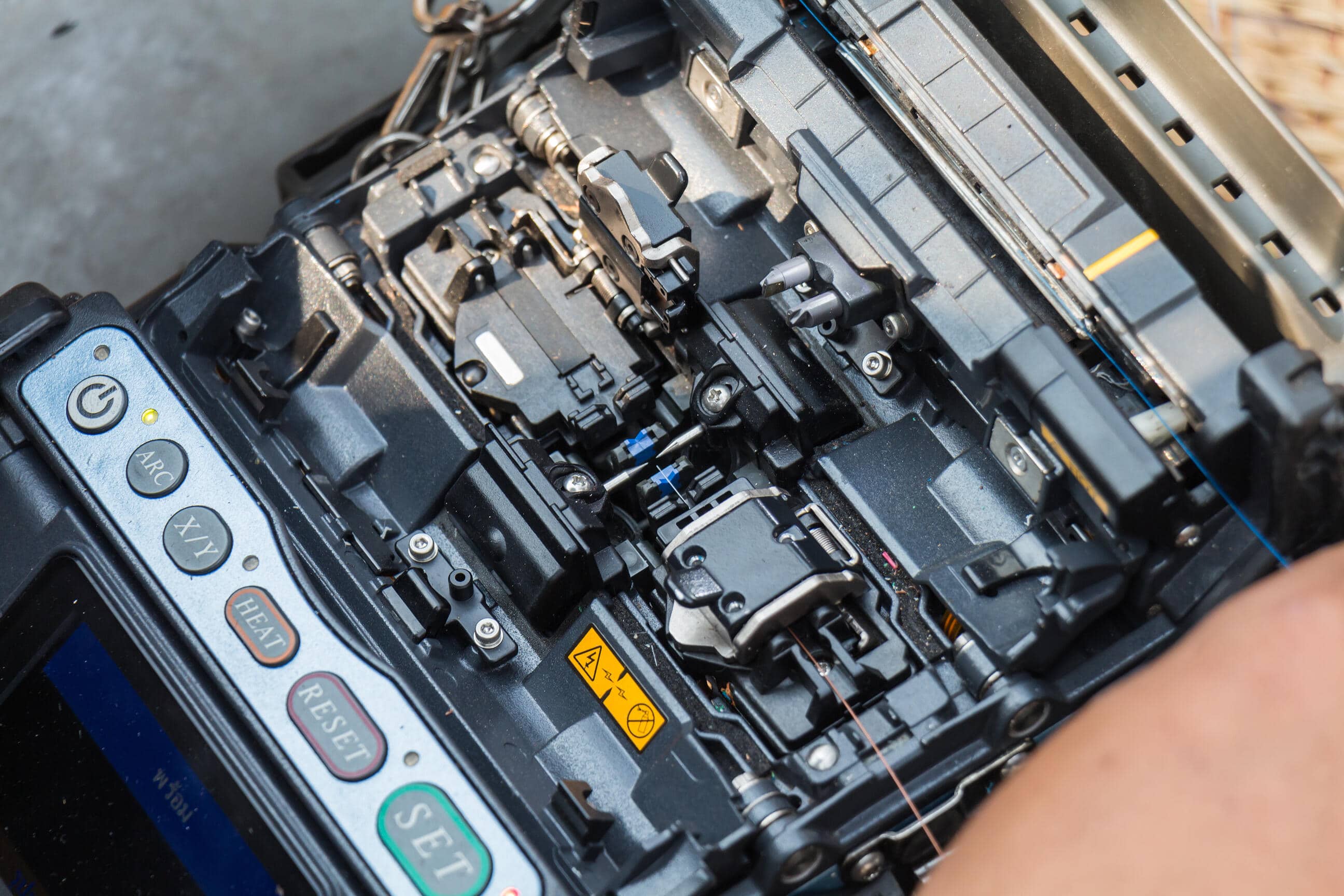
Fusion Splicing Step 3 – Aligning & Fusing

Next, you’ll be going through the aligning and fusing steps which involves positioning each cleaved fiber in place and fused. In most fusion-splicing machines, there’s a magnifying window or viewer that allows the fiber ends to be precisely positioned more easily. Exact positioning is the aim so that the light can pass through with minimal distortion, reflection or loss of signal. Once the correct alignment is achieved, the two ends of the fiber are melted together with a high-voltage electric arc.

Fusion Splicing Step 4 – Fiber Protection

The new fiber connection now needs to be protected, so that its integrity is maintained when it’s handled. Fusion splices typically have a tensile strength of around 0.5-1.51lbs and aren’t damaged by day to day handling. However, joins still need to be protected against bending and pulling forces that occur when they’re moved around.

Protection is typically achieved by placing a splice closure around the connection, which is then heat shrunk into place.

The Mechanical Splicing Steps

We’ll skip to step three at this point, as step one and two are the same as with fusion splicing.

Mechanical Splicing Step 3 – Joining the Fibers

Unlike with fusion splicing, you’re not permanently connecting the fiber ends together, so it requires no heat. The equipment used for mechanical splicing contains an index matching gel, which helps to match the index of refraction of the fiber cores. This helps to lower the loss of the connection.

Mechanical Splicing Step 4 – Fiber Protection

A separate step isn’t strictly necessary for fiber protection with mechanical splicing, as the mechanical splicer is a protector in itself and does so automatically.

Choosing Between the Two

The factors that will determine which of the two methods you use will boil down to performance and cost. While there’s a higher initial outlay for fusion splicing equipment, the value of each splice tends to be much lower than mechanical splicing. If you do much splicing, then the fusion method can work out less expensive in the long term, but if you don’t, then mechanical splicing comes into its own.

Performance

Insertion loss (loss of signal power) is higher with mechanical splicing at around 0.2bB-0.75bB, and this is because the fibers are technically just aligned and not connected physically. Insertion loss with fusion splicing is typically less than 0.05dB – primarily because the physical connection offers a more permanent, exacting connection.

Summary

Mostly, the benefits of fusion splicing over mechanical splicing are improved reflectance performance, and lower loss, which is why many Community Access Television (CATV) and telecommunication companies choose to use it for their long haul networks.

However, these same companies may use a combination of both methods in their local cable runs, with fusion splicing being applied in networks that use analog video signals that call for minimal reflection. Mechanical splicing is often the preferred choice when a signal loss is not such a significant concern – something that can be said for the majority of LAN applications.

It would seem that if initial cost was not a consideration, the fusion method is far superior regarding performance, protection and per splice expense, so there’s not much of a debate to be had about which is best. However, when a minor signal loss isn’t a big issue, then mechanical splicing is a more than a viable option – so long as the amount of connections being created isn’t excessively high, making the per splice cost prohibitive.

Common network cabling problems


As with many business technologies, there’s no such thing as a one-size-fits-all solution to small- and medium-sized businesses’ (SMBs) networking needs. However, there is one thing that holds true for all networking infrastructures: A highly efficient, well-functioning network relies on a well-structured cabling system.

If your SMB has been experiencing slow internet connections or total connectivity loss, bringing your business to a grinding halt, you may have improper cabling to thank. And since network issues are some of the biggest productivity killers in any organization, it’s a no-brainer that you should partner with a reliable managed services provider (MSP) to handle your structured cabling problems, which includes the following:

Your cabling does not meet standards

Your network’s cabling must meet the performance standards set by the Electronic Industries Association (EIA) and the Telecommunications Industry Association (TIA). Most manufacturers meet these requirements, but there are some that exceed minimum standards, providing consumers with cabling that can support their bandwidth needs for years.

Your network’s inefficiency may be caused by cables that don’t comply with the latest EIA/TIA standards. If your cables aren’t Category 6 and 6A (Cat 6 and 6A), which have been increasingly used in recent years, then that’s probably why your network is underperforming. Cat 6 cables can support bandwidths of up to 250 megahertz (Mhz), while Cat 6A can support up to 500 MHz.

Additionally, it may be that your cables are made of copper clad aluminum (CCA) rather than solid copper. While definitely cheaper, CCA cables are not compliant with EIA/TIA standards. They also oxidize and corrode easily, which causes failed terminations that lead to connectivity issues.

Your cabling is outdated

It really shouldn’t come as a surprise that old cables, particularly your backbone cable, can cause network problems. The backbone cable connects your network to the internet, bringing in signals from your internet service provider to all users on your network. If it’s been five or more years since it was installed, it most likely doesn’t meet current bandwidth standards, causing bottlenecks and sluggishness. And if you have a lot of users, or if they access bandwidth-heavy apps or websites, these problems may be exacerbated and lead to complete downtime.

The cables and connectors are not compatible

Using different components from different manufacturers may cause compatibility issues that are sure to affect your network’s performance. This is especially true if they weren’t designed and manufactured to work with one another. You may also experience glitches in your network if you use cables and connectors with different performance levels. Even the highest-quality cables can’t deliver the performance level it promises if the plugs and jacks they’re connected with can’t support them.

The patch cords are of poor quality

Many SMBs operate on tight budgets and are always looking for ways to save a buck. But patch cords for your network aren’t something to skimp on. Just like copper clad aluminum cables, cheap patch cords can save you money, but they may not be manufactured according to EIA/TIA standards and cause performance problems down the road. Repairing or replacing them also costs a lot, so you may end up spending more money than if you’ve had high-quality patch cords installed in the first place.

The cables are not properly installed

Improper installation, whether it’s due to your IT guy’s lack of training or an honest mistake, can result in even more expensive, time-consuming network reliability issues in the long run. One common installation mistake to look out for is running data cables parallel to electrical wiring. The magnetic field generated in electric wiring can interrupt the signals in data cables, crippling network performance.

Proper cabling is key to a reliable, efficient network. Nye Technical Services (NTS) will provide you with the comprehensive cabling services and networking solutions you need to achieve just that. Since 2009, NTS has been trusted by SMBs in Pennsylvania, Ohio, West Virginia, Maryland, and New York to provide top-of-the-line cabling and networking services at affordable rates. Talk to our experts at NTS and see how we can work together.

UTP, S/UTP, FTP, STP AND SFTP

When it comes to copper cabling, choosing the level of shielding you want the cable to have can prove a minefield of confusing acronyms and perplexing industry technology. We’ve put together this handy guide to help you understand the meaning of some of the most common terms.

The shielding inside your cable acts as a barrier to protect the cable from electromagnetic interference (EMI), radio frequency interference (RFI) and crosstalk between pairs and adjacent cables. It also prevents the signal from the cable interfering with surrounding equipment. The various levels of shielding offer a range of different advantages suitable for a number of applications.

U/UTP: UNSHIELDED TWISTED PAIRS

Also known as UTP, this is currently the most common and basic method of cable construction, consisting of pairs of wires twisted together. There is no shielding, instead the symmetrical twist in the wires create a balanced transmission line, helping to reduce electrical noise and EMI. In addition, the different twist rates of each pair can be used to reduce crosstalk. In higher category cables, a cross-web filler may be found separating the individual pairs to help reduce alien crosstalk from adjacent cables.

F/UTP: FOILED WITH UNSHIELDED TWISTED PAIRS.

Often referred to as FTP, this type of cable features an overall foil shield wrapped around unshielded twisted pairs and a drain wire. When the drain wire is correctly connected, unwanted noise is redirected to ground, offering extra protection against EMI/RFI.

S/UTP: SHIELDED WITH UNSHIELDED TWISTED PAIRS.

This cable construction has an overall braid screen with unshielded twisted pairs. This cable is often referred to as an STP, however this term should be used with caution due to other shielded cables also using this term. Always check whether the cable will have any shielding and whether individual pairs have their own shield. The cable is capable of supporting higher transmission rates across longer distances than U/UTP and provides better mechanical strength and grounding due to the braid.

SF/UTP: SHIELDED AND FOILED WITH UNSHIELDED TWISTED PAIRS.

This cable has both an overall braid shield and foil shield with unshielded twisted pairs. This cable offers effective protection from EMI both from the cable and into the cable as well as much better grounding due to the additional braid.

U/FTP: UNSHIELDED WITH FOILED TWISTED PAIRS

This type of cable has no overall shielding but the individual twisted pairs are wrapped in a foil screen, offering some protection from EMI and crosstalk from adjacent pairs and other cables.

F/FTP: FOILED WITH FOILED TWISTED PAIRS

This type of cable features an overall foil shield with individually foil tape shielded twisted pairs. These are similar to F/UTP cables, with the addition of a foil shield around each twisted pair. The cable construction is designed to provide the assembly with greater protection from crosstalk from adjacent pairs and other cables, RFI and EMI.

S/FTP: SHIELDED WITH FOILED TWISTED PAIRS

Similar to F/FTP, the individual twisted pairs are wrapped in a foil tape before being wrapped in an overall flexible yet mechanically strong braid screen. The additional foil on the twisted pairs helps to reduce crosstalk from adjacent pairs and other cables. The braid provides better grounding.

SF/FTP: SHIELDED AND FOILED WITH FOILED TWISTED PAIRS

Offering the maximum protection from RFI/EMI, crosstalk and alien crosstalk, this cable has both an overall braid shield and foil shield, with individually foil tape screened twisted pairs. This type of cable provides the best level of protection from interference and better grounding due to the braid.

Common Industry Acronyms  ISO/IEC11801 Name  Cable Shielding Type  Twisted Pair Shielding Type  Example
 UTP  U/UTP  None  None uutp
 FTP, STP, ScTP  F/UTP  Foil  None futp
 STP, ScTP  S/UTP  Braiding  None sutp
 SFTP, S-FTP, STP  SF/UTP  Braiding & foil  None sfutp
 STP, ScTP, PiMF  U/FTP  None  Foil uftp
 FFTP  F/FTP  Foil  Foil fftp
 SSTP, SFTP, STP, PiMF  S/FTP  Braiding  Foil sftp
 SSTP, SFTP  SF/FTP  Braiding & foil  Foil sfftp

Reference: universal networks

UPC or APC

UPCScreenshot 3

Ultra Physical Contact (UPC) connector. This results in a lower back reflection (ORL) than a standard PC connector, allowing more reliable signals in digital TV, telephony and data systems, where UPC today dominates the market.

Most engineers and installers believe that any poor performance attributed to UPC connectors is not caused by the design, but rather poor cleaving and polishing techniques. UPC connectors do have a low insertion loss, but the back reflection (ORL) will depend on the quality of the fiber surface and, following repeat matings/unmatings, it will begin to deteriorate.

APC

Angled Physical Contact Connector

So what the industry needed was a connector with low back reflection, that could sustain repeated matings/unmatings without ORL degradation. Step forward the Angled Physical Contact (APC) connector.

Although PC and UPC connectors have a wide range of applications, some instances require return losses in the region of one-in-a-million (60dB). Only APC connectors can consistently achieve such performance. This is because adding a small 8° angle to the end-face allows for even tighter connections and smaller end-face radii. Combined with that, any light that is redirected back towards the source is actually reflected out into the fiber cladding, again by virtue of the 8° angled end-face.

It is true that this slight angle on each connector brings with it rotation issues that Flat, PC and UPC connectors simply don’t have. It is also the case that the three aforementioned connectors are all inter-mateable, whereas the APC isn’t. So, why then is the APC connector so important in fiber optics?

The uses of APC connectors

The best feedback examples from my previous blog came from people experienced with FTTx and Radio Frequency (RF) applications. The advance in analogue fiber optic technology has driven demand for it to replace more traditional coaxial cable (copper). Unlike digital signals (which are either ON or OFF), the analogue equipment used in applications such as DAS, FTTH and CCTV is highly sensitive to changes in signal, and therefore requires minimal back reflection (ORL).

APC ferrules offer return losses of -65dB. In comparison a UPC ferrule is typically not more than -55dB. This may not sound like a major difference, but you have to remember that the decibel scale is not linear. To put that into context a -20dB loss equates to 1% of the light being reflected back, -50dB leads to nominal reflectance of 0.001%, and -60dB (typical of an APC ferrule) equates to just 0.0001% being reflected back. This means that whilst a UPC polished connector will be okay for a variety of optical fiber applications, only an APC will cope with the demands of complex and multi-play services.

The choice is even more important where connector ports in the distribution network might be left unused, as is often the case in FTTx PON network architectures. Here, optical splitters are used to connect multiple subscriber Optical Network Units (ONUs) or Optical Network Terminals (ONTs). This is not a problem with unmated APC connections where the signal is reflected into the fiber cladding, resulting in typical reflectance loss of -65dB or less. The signal from an unmated UPC connector however, will be sent straight back towards the light source, resulting in disastrously high loss (more than 14dB), massively impeding the splitter module performance.

compare

Picking the right physical contact connector

Looking at current technology, it’s clear that all of the connector end-face options mentioned in this blog post have a place in the market. Indeed, if we take a sidestep across to Plastic Optical Fiber (POF) applications, this can be terminated with a sharp craft knife and performance is still deemed good enough for use in the high-end automotive industry. When your specification also needs to consider cost and simplicity, not just optical performance, it’s hard to claim that one connector beats the others. Therefore whether you choose UPC or APC will depend on your particular need. With those applications that call for high precision optical fiber signaling, APC should be the first consideration, but less sensitive digital systems will perform equally well using UPC.

There is no doubt that the optical performance of APC connectors is better than UPC connectors. In the current market, the APC connectors are widely used in applications such as FTTx, passive optical network (PON) and wavelength-division multiplexing (WDM) that are more sensitive to return loss. But besides optical performance, the cost and simplicity also should be taken into consideration. So it’s hard to say that one connector beats the other. In fact, whether you choose UPC or APC will depend on your particular need. With those applications that call for high precision optical fiber signaling, APC should be the first consideration, but less sensitive digital systems will perform equally well using UPC.

LSZH or PVC

LSZH—Short for low smoke zero halogen, LSZH is a kind of cable built with a jacket material free from halogenic materials (such as chlorine and fluorine), since the toxic nature of these chemicals when burned. The term “low-smoke, zero-halogen” describes two distinct properties of a cable compound. The term “low- smoke” describes the amount of smoke which a compound emits when burned, while “zero-halogen” describes the amount of halogens used to make the compound. Terms like LSOH, LSHF and LSNH are all proper references for cables possessing low-smoke and zero-halogen properties.

PVC—Polyvinyl chloride (vinyl), a general-purpose plastic jacket material used for cables. Features low in cost and flexible, PVC cable is widely used in applications such as computers, communications and low voltage wiring. In the world of cabling, “PVC” is often used to denote a cable that is not suitable for use in a plenum airspace. PVC can potentially be dangerous in a fire situation, releasing heavy smoke and hydrogen chloride gas, which poses a great threat to human health electronic devices. PVC cables often have a CM, CMG, or CMR rating as defined by the National Electrical Code (NEC).

Differences Between LSZH and PVC Cable

Judging from the physical appearance, the difference between LSZH and PVC cable is very distinct. A PVC cable feels soft and it is smooth, whereas an LSZH cable feels rough since they contain the flame retardant compound and it is stiffer. LSZH cables are more aesthetically appealing than PVC cables. In addition to this, LSZH cable differs from PVC one in at least three aspects:

Cost: LSZH cables are slightly higher in cost than some PVC cables, but they are much safer when it comes to human health and sensitive and expensive electronic equipment. And this should be considered when comparing the cost.

Flexibility: Comparing with PVC compounds, there is a limited range of compound flexibility available for LSZH compounds, so LSZH cable is not recommended for robotic or continuous flex applications.

Heat: When a PVC cable is set on fire, it emits chemical fumes, acids and other toxic gases, which are both corrosive and harmful to human beings and environments. As for LSZH cable that has a flame-resistant jacket, it doesn’t emit these chemical substances even if it burns or exposed to high sources of heat. And it can reduce the amount and density of the smoke.

When Do I Use LSZH or PVC?

It is feasible that LSZH and PVC have equally effective performance in modern buildings. So the decision on which one to choose actually depends on the situation, that is to say, where you are going to run the cable.

PVC cable has been used in built environment for power and control applications for decades. It is commonly used for horizontal runs from the wiring center, or for vertical runs between the floors—but only if the building features a contained ventilation system running through the duct work.

LSZH cable would be more appropriate for places where fire presents a hazard to occupants. We known that the primary danger in the event of a fire is not the fire itself but the smoke and gas produced. Therefore, it is vital that the materials and products that are installed contribute as little smoke and gas as possible when burnt. LSZH cable can be employed in the following situations:

Confined spaces with large amounts of cables in close proximity to humans or sensitive electronic equipment, such as submarines and ships.
Mass transit, central office facilities and telecommunication applications.

Data Cabling

The installation, material, quality of cable and testing procedures are all much more critical in data wiring than in voice. The main reason for this is that networks today are designed to carry large amounts of information at incredible speeds.

To accomplish this over unshielded twisted pair cable (UTP), many different criteria must be met. This is why it’s crucial that your cabling design and installation is overseen by manufacturer-trained personnel who will ensure that your data cabling installationmeets all the performance specified by the standards.

Certified by every major manufacturer, LANSource can provide certified systems with applications warranties up to 25 years. We engineer and install industry standard Copper Data Cabling Systems to provide you with solid low-voltage infrastructure for voice, data, video, CCTV, access control, and building automation systems.

Today’s network cabling systems have to cope with the ever-growing demands of greater and greater bandwidth absorption within the local area network.  LANSource have years of experience in designing, implementing, and project management from small to large scale Data Cabling System comprising:

Category 5E

Cat 5e cable is an enhanced version of Cat 5 that adds more stringent specifications for far end crosstalk. It was formally defined in 2001 in the TIA/EIA-568-B standard, which no longer recognizes the original Cat 5 specification. The tighter specifications associated with Cat 5e system make it an excellent choice for use with 100Mbps Ethernet and basic voice services.

Category 6

(ANSI/TIA/EIA-568-B.2-1) is a cable standard for Gigabit Ethernet and other network protocols that is backward compatible with the Category 5/5e and Category 3 cable standards. Cat-6 features more stringent specifications for crosstalk and system noise. The performance headroom provided by category 6 solutions makes it a reliable and safe choice to support all Class E applications including 1000Mbps Gigabit Ethernet, PoE and PoEP.

Category 6A

Augmented Category 6 / Class EA, structured cabling is specified by cabling standards ISO/ IEC 11801 :2002 amendments 1 and 2 (Class EA) and TIA 568C (Augmented Cat6). The specifications of Cat.6A allow it to fully support 10GBASE-T applications in the Data Centre or desktop. Cat.6A is available in both shielded and unshielded system.

Category 7

Category 7 cable (CAT7), (ISO/IEC 11801:2002 category 7/class F), is a cable standard for Ethernet and other interconnect technologies that can be made to be backwards compatible with traditional CAT5 and CAT6 Ethernet cable. CAT7 features even more stringent specifications for crosstalk and system noise than CAT6. To achieve this, shielding has been added for individual wire pairs and the cable as a whole. CAT7 cable is rated for transmission frequencies of up to 600 MHz and supports high bandwidth and high frequency multi-media broadcast and cable sharing applications.

Why Your Network Cable is Slowing You Down

We were recently perusing facebook and came across an article written and shared by our friends over at Blue Jeans Cable, entitled, “Is Your Cat 6 Cable a Dog?”. We were pretty shocked to discover that 80% of the cables they tested didn’t pass rated spec. So, we shot an email to Kurt Denke, President of Blue Jeans Cable, requesting to do an interview on the topic of network cables, quality control, and how it all relates to home theater consumers and customer installers.

While we have covered the difference between HDMI and speaker cables to death, we have never really thought about or written anything about network cables. However, with the advent of Baluns that use network cables to transmit all types of AV signals over great distances, and the promise of wide HDbaseT support in the near future, we figured it was time to jump into the facts and fiction surrounding yet another cable type. Network cabling is now an integral part of any modern AV system, but there is a lot more to it than most people think. Read on to see what one of the most reputable cable manufacturers has to say on the topic.


AH: First off, Can you tell us the differences between Cat5e, Cat6, and Cat6a cables?

Kurt: Well, on superficial physical examination, there’s very little difference at all, other than that 6 and 6a typically have higher twist rates and a pair-separating spline; but electrically, there is a big difference and it all has to do with bandwidth.  The more data you want to shove through a cable, the higher the frequency of the signal is, and a data pair whose dimensions and spacing are consistent enough to handle ten Megahertz won’t necessarily do at a hundred Megahertz because the materials and dimensions become increasingly critical at higher frequencies.  It’s all about tolerances.  Cat 5e cable has got to meet specification requirements up to 100 MHz; Cat 6 takes the spec tighter AND increases that to 250 MHz; and Cat 6a takes it out to 500 MHz.  To handle 500 MHz well on a balanced feedline like that is quite a trick.

AH: Is there any kind of licensing organization or governing body for regulating network cable quality?

Kurt:  Oddly enough, no.  There are two versions of the specification–one from TIA and one from ISO–but there is no enforcement organization or licensing involved.  There’s nothing to prevent somebody from labeling cable with any “category” he wants to label it with, and people do; we see cable that badly fails 5e labeled as 6.  We’re also seeing a lot of Nigel Tufnel-ism in cable labeling–cable labeled Cat 7 with RJ-45 connectors, which aren’t Cat 7 compliant–but just as 11 is higher than 10, I suppose 7 is higher than 6.  The question people forget to ask is the question Nigel Tufnel forgets to ask: what does the higher number mean, and is the thing it labels actually better?  Our testing suggests that more effort sometimes goes into the jacket lettering than into cable quality.  


AH: In basic terms, what does it mean if a cable fails the test?

Kurt: A cable fails, usually, for one or both of two reasons.  Either the crosstalk, which is the tendency of signals on the various pairs to interfere with one another, or the return loss, which is the loss associated with impedance instability, are too high.  Where crosstalk is one pair interfering with another, return loss is more like the signal on the pair bouncing around and interfering with itself–it’s a rather counterintuitive notion for people who are not used to thinking in terms of high frequencies and transmission line theory, but in these types of applications it’s very real and it will really mess with the signal.  With enough crosstalk or return loss, data become unrecoverable from the signal.    


AH: What kind of effects would a failed cable have in real world use?

Kurt: At the outset, you’re going to have dropped packets which devices will have to resend, so network bandwidth is getting eaten up by repeating information that didn’t get through the first time.  If there are enough dropped packets, what most network devices will do is turn down the data rate, since a network that fails to work well at full speed may work just fine at a slower speed.  Either way, the network runs slower and/or less reliably. 

Last week I had an interesting conversation with a technical rep at Fluke, who explained to me that under some conditions, it can be much worse.  I didn’t quite grasp all the details, but the essence of it was that if network switches are set up correctly, a bad link will have its speed turned down but the rest of the network will run full speed.  If they’re not–which he seemed to think was not terribly unusual–the switch can turn down the speed of every line due to one bad link.  So, one guy puts a lousy patch cord in to his computer, and his whole node slows down.  


AH: What if you spend more on network cables, does that indicate any better quality?

Kurt: Mostly no, but a qualified yes, which I’ll have to explain. 

We have always said, and this is true for Ethernet as well as for other products, that price is a very, very poor proxy for quality.  When we went out to test Ethernet cables, some of the most expensive ones we bought were the absolute bottom of the barrel–as were some of the cheapest.  There seemed to be no dependable pattern except that, at all price levels, performance was mostly horrible.

Now, price does come into it in one sense.  The cheapest spec-compliant cables cost more than the cheapest non-compliant cables.  But trying to find quality by searching price is a fool’s errand, because most of the expensive cables aren’t compliant, either.  You’ve got to buy from somebody who actually tests each assembly, and tests it properly. There are a number of vendors who do, but many or most people reading this interview will not have heard of any of them.  Their products don’t normally sell at retail stores or through popular web merchants, but are found at large electronic distributors catering to such markets as the commercial integrator, data center, and broadcast markets.  They don’t have a lot of interest in the consumer market, largely because these commercial customers often buy thousands of cables at once while you and I are likely to buy one or two.  


AH: Is there anything a consumer or custom installer can do to ensure they are buying quality network cables?

Kurt: You’ve got to know your vendor’s quality control practices.  All of the quality vendors test every assembly; we’re the only one I know of who stick the test report on the bag, but if you’re dealing with somebody like, say, Belden (NOT to be confused with Belkin!), who supply us our cable stock, they will tell you that they do test every assembly.  We’ve tested their patch cords, and sure enough, they are consistent, high quality patch cords, in part because they do test every assembly; but again, you won’t see their product anywhere you’re likely to shop. 

Even on vendor quality control, regrettably, you’ve got to be specific.  My Fluke contact tells me there are vendors who will sell what they call “channel-compliant tested” cables.  What this means is that the cable was tested to the “channel” standards in the spec rather than to the patch cord standard.  It’s a complicated subject, but the summary is that the channel standard is not the applicable spec, and is much, much, much easier to pass.  A cable with RJ-45 connectors on each end that doesn’t pass the patch cord spec is non-compliant, period, end of story, without regard to whether it would pass the inapplicable channel test.


AH: We’ve noticed that you can buy stranded or solid network cables, you do you have any advice?

Kurt: Impedance stability’s a bit easier to achieve in solid conductors, but stranded conductors will give the cable higher flexibility and flex-life.  However, the flex life of solid copper conductors is excellent, so unless you’ve got a constant-flexing sort of application like a robot arm or you need what they call “tactical” cable, which is high-flex and high-durability, we generally recommend solid conductors. 


AH: What about bulk cable and connectors?


Kurt: At this point we haven’t tested bulk cable available from hardware stores and the like, but our test results on patch cords were so horrifying that we would be surprised if the Cat 5e and 6 cable at the hardware stores turned out to be up to spec.  I have been assured by engineers who have tested bulk cable that there is a lot of 85-ohm network cable out there; that is. it’s widely off the specified 100 ohm impedance, and will fail no matter how well it’s installed and/or connectorized.   Again, there are vendors who make the good stuff.  In the USA there’s Belden, whose cable we use; there are some others that are well regarded, such as Gepco; but I would stay away from the kind of generic Chinese stuff the hardware stores carry unless and until I could have it validated through testing.  The good stuff doesn’t have to be particularly expensive; Belden 1583A is quite economical standard Cat 5e, for example, and it’ll cost more than the hardware store stuff but it really does meet spec. 

AH: When making your own cables, are there any best practices to follow (MBR, crimping, unfolding at crimp, strain)?

Kurt: Assuming that good quality cable and connectors are being used (a big, important assumption!), the termination practices make all the difference in the world.  The most important thing to do is to try not to have to untwist a lot of length of wire, because untwisting excessively will cause return loss and crosstalk issues.  You also want the jacket to extend up into the back crimp area so that stress on the cable is carried by the jacket.  Try to confine the un-twist region to the visible cable (that is, don’t allow the untwist to “propagate” up under the jacket), and try to get that as short as you can.  Some types of connectors use a “load bar” which makes this much easier to do.

On MBR (minimum bend radius), the main thing is not to kink the cable; a little over-bending won’t usually destroy cable, but you don’t want to bunch it up and when you have to shorten it, it’s better to do it in a round coil than any other configuration.  Some cables from Belden use bonded pairs, which are nice because they are a bit more stable when flexed–that’s what we use for most of our assemblies.   

How successful you will be at making compliant cables depends not only on your practices but also on the “category” because how critical termination is varies quite a bit.  Our experience, validated by our experience and the tester, runs like this:

  • Cat 5e: good cable and connectors, plus good termination practices, means you will almost never make a bad cable.  Even without a tester to guide you, you’ll probably hit 100% compliance.
  • Cat 6: good cable and connectors, plus good termination practices, will not get you to 100% compliance unless you can test cables and learn from the feedback the tester gives you.  However, once you do learn how to make compliant cables, you will be close to 100% compliant and rarely have to reterminate a cable.
  • Cat 6a: for the uninitiated this can be a vale of tears.  Good cable and connectors, and good termination practices, are no guarantee and even after you have learned best practices you will still make some bad cables and have to reterminate.  Without a very sophisticated tester, you won’t know which ones are bad, and without the feedback you get from such a tester, you may well never make a compliant cable at all. 


AH: Do you have any opinion on EZ RJ45 (pass-through) connectors vs standard RJ45 ends.

Kurt: If by this you mean the RJ-45 connectors where the conductors feed through and are cut off, those can be handy if you’re making Cat 5e patch cords from high-flex stock, which otherwise can be surprisingly difficult due to the tendency of the conductors not to stay in order while sliding into the back of the connector.  But the tiny bit of extra wire, though it may look like nothing, presents a big impedance bump and reflection point for high-frequency signals and I wouldn’t ever use those for anything beyond 5e.  A better way to go, if you need easy termination, is a connector with an internal load bar which allows you to line the conductors up very close to the termination point. 

Edit: After the interview, I remembered that we still have (we don’t use them any longer) some of the pass-through type RJ-45 plugs for Cat 5e.  I made two cables, each five feet long, using Belden 1700A (Cat 5e bonded pair cable); one used the pass-through plugs and the other used our standard plug.  The pass-through cable passed 5e testing, but with only 0.4 dB of clearance on near-end crosstalk (NEXT), which is within our tester’s margin of error–that is, the tester says it passed but it’s too close to be completely sure.  The conventional connector passed by 3.0 dB — more than seven times the clearance, and well outside the tester’s margin of error.  That’s not a small difference, and it does indicate that one is giving up a bunch of headroom, at least, using the pass-through type connectors.  Now, to make this a statistically valid test I’d have to build a bunch more and compile all the results together–but this is what engineers whose judgment I trust have told me about these, so I suspect it’s fairly representative.


AH: Apart from spending $12,000 on test equipment like you, what can an average person do to test cable compliance or quality?

Kurt: Very little, unfortunately.  There are cheaper test appliances such as the ones Fluke calls “qualification testers,” but those do not run the tests required to fully certify compliance, and they’re still very pricey.  The only really affordable testers are the continuity-and-short checkers, but those tell you nothing whatsoever about high-frequency performance–they just tell you that all the wires are hooked to the right pins. 

You’ve got to know, as I said, your vendor’s quality control practices.  Most of the online vendors of data cabling simply don’t have any idea whether their cable is compliant, or even know how to check.  They bid this stuff out to Chinese factories and the whole process of product selection winds up being highly price-driven rather than quality-driven.  Even a good assembler like us cannot guarantee that every assembly we build will be compliant–but what we can do is test every assembly before it goes out, and fix or discard the bad ones, so that we can guarantee that every assembly we sell is compliant.


AH: Do you have anything else you would like to add?

Kurt: To me the most surprising result of our testing was that not only did the Cat 6 cables we tested routinely fail Cat 6 standards, but just over half of them failed Cat 5e standards, in some cases quite badly.  We know how easy it is to make compliant Cat 5e cables–I could teach anyone in fifteen minutes–and so we had assumed that even if these cables failed their stated standard, they’d certainly at least pass Cat 5e.  That they do not is frankly shocking.  It shows that quality control must not be merely lax, but must be nonexistent, at many of the Chinese factories where these assemblies are being made.  The upshot is that people who are paying extra for Cat 6 and 6a assemblies, and who think that they are paying that little extra for the sake of “future proofing,” not only are not getting the future-proofing they’re paying for but are in many cases getting cables so bad that they may be choking the customer’s existing Cat 5e network.  Not one vendor we tried had consistently passing scores, and well-known brands failed as badly as less-known ones. 

The United States is still the world’s greatest manufacturing nation when quality, and not just price, is at issue.  My commitment to keeping manufacturing jobs in America isn’t just based upon national pride; it’s about having quality goods we can stand behind, made by employees who are skilled at what they do and who earn a true living wage.  Many people buy Chinese goods because they assume that the quality is acceptable despite the low price.  For some kinds of goods that may be true; for Ethernet cable it is demonstrably false.   

reference: https://www.audioholics.com/audio-video-cables/bjc-cat-network-cable-quality-interview

Benefits of Structured Cabling

Every year, our world becomes more connected through advancements in technology. Businesses are always looking for the best solutions for their telecommunications systems, which need to be effective, yet low-maintenance. Traditional point-to-point systems not only create a jungle of wiring, but they also can’t carry ever-increasing data at high rates. That’s where structured cabling systems come in. They are the foundation of your company’s communications infrastructure and their benefits cannot be ignored. A structured cabling system ensures all of your communications needs — for telephone networks, video surveillance, etc. — are met efficiently, streamlining your entire IT network in a way that the traditional point-to-point system simply cannot do. So what are the major benefits of structured cabling systems? We’ve got five answers.

1. It’s Simpler to Manage

You won’t need to continually call on a big team to keep your data center cabling under control, as it can be administered and managed by minimum staff. When changes do need to be made to the system, they can be done in a faster, more efficient way, with minimal disruption.

2. Your Company Will Get a Higher Return on Investment

A structured cabling system unifies your IT network for data, voice and video. That unified structure reduces the need for updates and lowers your maintenance costs. Additionally, any additions, moves or changes can be made within the system with ease, saving your company both time and money.

3. All IT Infrastructure Will Be Better Prepared for Expansion

Structured cabling comes with a high bandwidth. That means it will be able to support future applications your company may decide to add, such as multimedia or video conferencing, with little interruption to your current system. As a result, you can rest assured knowing your system won’t become dated after just a few years. Instead, your system’s vast infrastructure will adapt with your telecommunication needs.

4. You Will Have More Flexibility Within Your System

Multiple wiring systems can be a headache. A structured cabling system, however, consolidates your wiring system into a single infrastructure that transfers data in multiple formats. This flexibility also makes the system easy to dismantle and move to a new location if needed.

5. Structured Cabling Is More Aesthetically Pleasing Than a Multiple Wiring System

Aesthetics matter, too. Structured cabling creates a cleaner, less cluttered look than a point-to-point cabling system. A cabling system plagued with wires left and right can slow functionality, but a unified system is more efficient and easy to use. The benefits of structured cabling simply can’t be underestimated when looking for the right telecommunications network for your company. If you want a simplified system with room to grow, one that maximizes functionality and saves your business both time and money, structured cabling is the way forward.


reference: http://www.abcomllc.com

CAT5e, CAT6, CAT6a and CAT7 Category Cable

For cabling and communications manufacturers, knowing the difference between different category cables (CAT5e, CAT6, CAT6A and CAT7) is easy. For those that are looking to use category cable to wire a home, office, data center or business, the performance ratings and variances between the cables can be confusing. To help Vericom Volt customers better understand the differences, we will review the capabilities of each category to help choose the right category cable for your installations. For each of the category cables we are referencing, the standards related to a maximum installation length of 100 meters (roughly 328 feet).

CAT5e:

CAT5e category cable supports speeds up to Gigabit (1,000 Megabits per second) Ethernet at 100 MHz. An enhancement of the previously released CAT5 cable, CAT5E (the E designates Enhanced) cable is similar in specifications to CAT5 cable, but has been enhanced to minimize crosstalk. In addition, CAT5e category cable is best suited for installations in networks that change frequently, such as servers with patch panels, home and business installations where you are plugging patch cord connections from computers into wall ports and other similar uses.

CAT5e is available in different configurations, including solid copper wire vs. stranded wire, as well as in shielded vs. unshielded variations. Shielded CAT5e is often used in situations where there may be a great deal of electromagnetic interference (EMI) from other devices in a home or office situation.

CAT6 and CAT6a:

Similar to CAT5e, CAT6 and CAT6a supports speeds over a Gigabit (1,000 Megabits per second) Ethernet, but the main difference from CAT5e is that CAT6 and CAT6a runs at a bandwidth of 250 MHz, which makes CAT6 and CAT6a ideal for business use. For homes and businesses that are looking to offer high performance connections, upgrading to CAT6 or CAT6a can help minimize issues with crosstalk and EMI on networks.

For those looking to offer a sense of “future-proofing” their home or business, CAT6 and CAT6a offer advantages over CAT5e. The higher bandwidth of these category cables can keep your networking setup at high performance levels as service providers offer continually higher speeds. In addition, CAT6 is suited for more permanent installations in home or offices, due to the ability for the

CAT6 and CAT6a are also available in solid copper wire vs. stranded wire, which offers different advantages. Solid cable consists of a single piece of copper for electrical conduction, while stranded cable use numerous copper wires stranded or twisted together for conductors. Stranded wire is best used for applications where flexibility is important, including desks and other areas of frequent movement, while solid cable is a better option for permanent installations, including walls and outdoor, where the durability of solid cable offers longevity versus flexibility.

CAT7:

The next iteration of category cable, CAT7, offers even higher levels of speed for users, with support up to 10 Gigabit (10,000 Megabits per second) Ethernet, with a bandwidth of 500 MHz. CAT7 cables offer exceptional data speed. CAT7 is designed to bring the highest possible speeds for business and server applications, while adding better resistance to EMI, high power ratings and less loss of voltage. For home use, CAT7 can also be beneficial for smart home installations related to whole home technology solutions.

WireXpert Approval Letter

https://itnetworks.softing.com/us/fiber-cabling/vendor-approvals/Commscope-psiber wirexpert 4500 approval letter