Category: Info

WireXpert VS Fluke DSX-5000

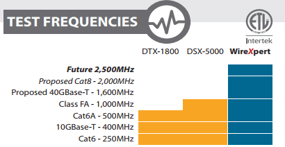
TEST FREQUENCIES

Screenshot 8


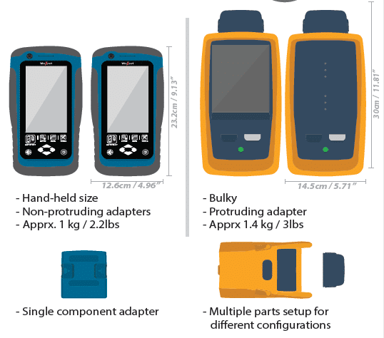
PHYSICAL COMPARISONS

Screenshot 9


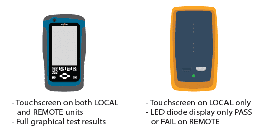
TOUCH SCREEN

Screenshot 10


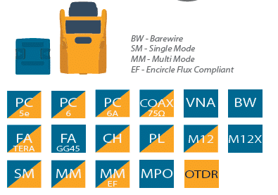
ADAPTER RANGE

Screenshot 11


MAINTENANCE

WireXpert
– Low cost for replacement
of PL test cords only
– Live and phone technical
support included
– Rugged industrial design
to reduce impact damage
DSX-5000
– High cost to replace PL
test cords with adapter
– Only with Gold support
plan
– Fragile and delicate
parts may crack after
multiple impacts

PC SOFTWARE

eXport for WireXpert
ref: eXport v7.1.292
– No previous Certiers
– Multilingual
– Supports *.PRX (native),
*.SOR (OTDR)
– Exports to *.PDF, *.CSV
– Exports to compressed
*.PDF les for small le size
– Supports inverted Y-axis
plots
– Supports re-certication
– Supports cable pairing
conversion between
T568A and T568B
– Supports remote display
for presentation purposes
– Generates customisable
hierachical based labels
for list based testing
(Bld/Fl/Tel/Rk/Pn/Prt)
– Generates labels for
point-to-point for
connections
(eg. a1/b2 to a5/b5)
LinkWare for DSX-5000
ref: LinkWare 9.3
– Backward compatible to
previous Analyzers
– Multilingual
– Supports *.FLW (native),
*.TST (native)
– Exports to *.PDF, *.CSV,
*.TXT, *.XML
– Does not compress
*.PDF le
– Does not support
inverted Y-axis plots
– Supports re-certication
– Does not support
conversion
– Does not support
remote display
– Generates basic
sequencial labels
(eg. a1-b5)

WireXpert alternative to Fluke

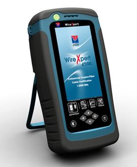
Psiber WX4500 WireXpert Cable and Network Analyzers

Certify your data center and enterprise installations in the shortest time The WireXpert with its unparalleled 2500 MHz measurement range is the first cable certifier with capability to certify the highest performance cabling systems in enterprise networks and data centres. Cable installers make significant gain in productivity with WireXpert‘s industry leading test speed and ease of use. With certification testing up to Class FA and CAT8 copper cabling as well as MPO SM and MM fiber optic cabling WireXpert is ready for 40G and beyond.

Dual control system allows engineers to control the tester and view or save results from both main unit and remote this makes it possible for one engineer to carry out tests reducing the time spend on site testing. Wide range of fibre optic test modules so the WireXpert is truly versatile tester with Psiber Data continually developing new products for example being the first manufacturer to develop MPO fibre testing for Data Centres using a standard cable tester.

Key Benefits

  • Permanent link adaptors have a replaceable permanent link cord so when the plugs are worn you do not have to replace the whole unit just the lead. Which means less down time and saves money  reducing the overall cost of ownership
  • Dual control system allows installers to control tester and view or save results from each end this makes it much possible for one engineer to carry out tests reducing the time spend on site testing
  • Tests Cat6A in under 9 seconds on Autotest reducing the amount of time spent testing on site allowing your engineers to be more efficient
  • Protects your Investment: Beyond 10G with CAT8 ready cable tester currently the only tester available that do this!
  • Approved by over 20 major cable companies worldwide including Commscope Brand-Rex Nexans and Excel
  • Wide range of fibre optic test modules so the WireXpert is truly versatile tester with Psiber Data continually developing new products for example being the first manufacturer to develop MPO fibre testing for Data Centres

Cabling systems are evolving rapidly with CAT8 standard for copper cabling on the horizon and rapidly growing use of MPO and Single Mode cabling for 40G Ethernet and beyond.  The powerful measurement engine of WireXpert 4500 performs the most complex cable certification tests accurately and in a matter of seconds you will know the answer to “PASS or not?” WireXpert 4500 is your best and probably the only investment in test instrument.  With a large number of application specific detachable test adapters you can test many different types of cables and components.

WireXpert 4500 has test adapters for all categories of copper patch-cords multi-mode MPO cables simplex multi-mode and single-mode links industrial Ethernet cabling systems (1G and 10G) coaxial cables and more. WireXpert 4500 even offers a range of specialised adapters for lab testing.  In fact some of the most reputed cable vendors use WireXpert 4500 in their research labs to qualify newly developed cabling components. We welcome you to experience the speed of testing accuracy and simplicity of WireXpert 4500!

Two Important Methods for Fiber Optic Splicing

Fiber optic splicing is an important method of joining two fiber optic cables together. It is a preferred solution when an available fiber optic cable is not sufficiently long for the required run. Besides, splicing is designed to restore fiber optic cables when they are accidentally broken. Nowadays, fiber optic splicing is widely deployed in telecommunications, LAN (Local Area Network) and networking projects. Typically, fiber optic splices can be undertaken in two ways: fusion splices and mechanical splices. This paper firstly illustrates the specific process of fusion splicing method and mechanical splicing method, then makes a comparison of the two methods for your reference.

Fusion Splicing Method

Fusion splicing is a permanent connection of two or more optical fibers by welding them together using an electronic arc. It is the most widely used method of splicing as it provides for the lowest loss, less reflectance, strongest and most reliable joint between two fibers. When adopting this method, fusion splicing machines are often used. Generally, there are four basic steps in fusion splicing process as illustrating in following one by one.

Step 1: strip the fiber

The splicing process begins with the preparation for both fibers ends to be fused. So you need to strip all protective coating, jackets, tubes, strength members and so on, just leaving the bare fiber showing. It is noted that the cables should be clean.

Step 2: cleave the fiber

A good fiber cleaver is crucial to a successful fusion splice. The cleaver merely nicks the fiber and then pulls or flexes it to cause a clean break rather than cut the fiber. The cleave end-face should be perfectly flat and perpendicular to the axis of the fiber for a proper splice.

Step 3: fuse the fiber

When fusing the fiber, there are two important steps: aligning and melting. Fist of all, aligning the ends of the fiber within the fiber optic splicer. Once proper alignment is achieved, utilizing an electrical arc to melt the fibers to permanently welding the two fiber ends together.

Step 4: protect the fiber

A typical fusion splice has a tensile strength between 0.5 and 1.5 lbs and it is not easy to break during normal handling. However, it still requires protection from excessive bending and pulling forces. By using heat shrink tubing, silicone gel and/or mechanical crimp protectors will keep the splice protected from outside elements and breakage.

Mechanical Splicing Method

If you want the splices to be made quickly and easily, the mechanical splice is a better choice. A mechanical splice is a junction of two or more optical fibers that are aligned and held in place by a self-contained assembly. A typical example of this method is the use of connectors to link fibers. This method is most popular for fast, temporary restoration or for splicing multimode fibers in a premises installation. Like fusion splice, there are also four basic steps in mechanical splice.

Step 1: strip the fiber

Fiber preparation here is practically the same as for fusion splicing. Just removing the protective coatings, jackets, tubes, strength members to show the bare fiber. Then ensuring the cleanliness of the fiber.

Step 2: cleave the fiber

The process is the same as the cleaving for fusion splicing. It is necessary to obtain a cut on the fiber which is exactly at right angles to the axis of the fiber.

Step 3: mechanically join the fiber

In this step, heating is not used as in fusion splice. Simply connecting the fiber ends together inside the mechanical splice unit. The index matching gel inside the mechanical splice apparatus will help couple the light from one fiber end to the other.

Step 4: protect the fiber

Once fibers are spliced, they will be placed in a splice tray which is then placed in a splice closure. Outside plant closures without use of heat shrink tubing will be carefully sealed to prevent moisture damage to the splices.

Which Method is Better?

Both fusion splicing and mechanical splicing method have their advantages and disadvantages. Whether choosing fusion splice or mechanical splice depends on the applications.

The fusion one provides a lower level of loss and a higher degree of permanence than mechanical splicing. However, this method requires the use of the expensive fusion splicing equipment. In view of this, fusion splice tends to be used for the long high data rate lines that are installed that are unlikely to be changed once installed.

The mechanical splicing is used for applications where splices need to be made very quickly and where the expensive equipment for fusion splices may not be available. Some mechanical fiber optic splice easily allows both connection and disconnection. In this way, a mechanical splice may be used in applications where the splice may be less permanent.

are share from: http://www.fiber-optic-solutions.com/two-important-methods-for-fiber-optic-splicing.html

Test Method Fiber Optic

Choose a Test Method.

image19
Once the test cords are verified, you may test the fiber link. There are three options for setting an optical reference between a source and power meter. These options may use 1, 2 or 3 jumpers, or Test Reference Cords. The method used is determined by your regional or vendor-specific requirements. A couple of things should be noted. Optical Loss Test Sets (OLTS) typically have a source and meter at EACH end so they measure two fibers at one time. For simplicity and clarity the graphics here are only showing a simplex setup – one light source to one power meter (except in testing setup with 2 reference cords, that shows both links). When the term “test reference cord” is shown this means a cord with “reference grade connectors”. These are connectors that provide much lower loss than “standard” connectors. Test reference jumpers are more expensive than regular patch cords. A couple of final notes on referencing: Regardless of vendor or model, all optical sources should be allowed to warm up for about 5 minutes prior to performing a reference. On most Optical Loss Test Sets designed for Tier 1 certification, there will be a setting for “reference method”. The physical configuration used to perform the reference MUST match the setting on the test device or your test margins are invalid. So if you set your test setup to do a three fiber reference but what you actually physically do is a one fiber reference, you have a completely invalid test result, especially your test margins are going to be completely invalid. NEVER disconnect the test jumper from the transmitter after a reference is performed – this will destroy the reference – you will need to do it again. Always check your reference by connecting the source test jumper to the power meter test jumper and perform a measurement. There is some variation in what you would expect to see when checking your reference – based on the quality of your test jumpers and the reference method used, certainly below 0.3 dB. One thing you want to watch for when checking your reference is ‘gainers’ – where your test set shows a loss with a positive value, +0.2 dB for example. That is also an indication that you’ve got a bad reference and you’ll need to redo your reference. It is a good practice to save your reference check to have proof that a good reference was established prior to testing. If during the course of testing you question your results, simply check your reference again and re-reference if needed, save the result and carry on testing.
referenece: commscope SP3802 training

Reasons Structured Cabling is Important for Business Phone Systems

Here are 5 reasons why structured cabling is essential for your business phone systems:

1. Faster transmission

When your team is on the phone waiting for an irate customer’s record to appear, every second can feel like an eternity. You’ll want to move data to the point of use as fast as you possibly can. Category 6A cable supports up to 10-Gigabits per second, while Category 5e supports 100 mbps. Most experts no longer recommend Category 3 for data transmission because of its slow speed and high volume of noise. Don’t slow down your business phone system and important data by using cables that won’t support the speed you need.

2. Less Noise

All twisted pair cable is susceptible to some degree of noise from nearby electronic equipment, but Category 5 is far superior to the older Category 3 at noise resistance. Category 5e, Category 6 and Category 6A each offers a big leap in noise reduction over its immediately preceding standard. Fiber optic cabling offers the best resistance to noise of any other cable system. Noise causes static and poor connections during phone conversations and corrupts data. Excessive noise slows down your network because the system has to resend corrupt data repeatedly until it gets through uncorrupted. It is a false economy to go with a lower quality cable, because you pay more in the hidden costs of slow response times and irritated customers.

3. Longer runs

The higher the quality of the cable that supports your business phone system, the longer the runs it can support without errors and artifacts creeping in. There are no restrictions on the length of fiber optic cable runs, and its superior noise resistance and speed make it an excellent choice for a business phone system or data center. Category 5 or category 6A wiring can support runs of up to 100 meters without noise, which gives you more flexibility in laying out your facility and reduces the number of repeaters or data hubs you’ll need to install. Eliminating hubs and repeaters as much as possible makes your network more reliable and reduces the investment in necessary equipment. Its reasonable cost coupled with the superior noise resistance over long runs makes Category 5e or Category 6A the cable of choice for Houston business phone systems.

4. Lower cost of maintenance

Fiber optic, Category 5e or Category 6 cables rarely go bad. On the rare occasion that they do, having a properly installed and carefully marked cable structure can make it faster to identify the problem and easier to replace the cable. Downtime equates to lost revenue, so you want to maximize uptime for your enterprise phone system in every way possible. In addition, instead of spending time tracing cables, your tech support or IT team can spend their time on more strategic initiatives than ensuring the integrity of your cables.

5. Position for growth

When they install NEC phone systems, Houston companies are making an investment in their future. By upgrading the structured cabling system that supports the digital phone system and the company’s data at the same time, these companies position themselves for growth with infrastructure that supports fast, error free transmission of voice and data. Houston business phone systems supported by fiber optic cables or the highest possible category of cable provide companies with superior speeds and voice quality that helps the company compete better in their industry. Better quality cabling is a better investment, because it will serve the company well for far longer than cheaper cabling, and it will be far less troublesome during its entire useful life.

Companies should install the best and most up-to-date data cabling they can afford to ensure that they get top performance from their digital phone system. Good quality cabling can reduce maintenance costs, increase data transmission speeds and improve voice quality.

Reference: http://www.ttihouston.com/blog/bid/324395/5-Reasons-Structured-Cabling-is-Important-for-Business-Phone-Systems

Why should keep your cable rack organize

One of the most challenging aspects of data center cabling is cable management. The concept is simple – dress the cables nicely and leave them that way. However, the data center environment is extremely dynamic and there are extremely short windows of time to work with the cables.

Plus, there are typically budget constraints that leave your installation team with very few options to get the job done properly.

We help you implement it. One of the benefits to a structured cabling system is the ability to keep a clean-looking data center and get rid of messy spaghetti cabling.

Our data center architects and infrastructure design specialists have years of first-hand experience and are always up-to-date on the latest standards. And we offer products that are built to last.

Because the environment is so dynamic, cables are unplugged and plugged in frequently. This type of activity can break many cables, but not ours.

How to Implementing Structured Cabling

The cabling infrastructure will be under a raised floor or overhead-or both. This is where the bulk of the horizontal cabling will be installed. Most likely you will hire a reputable cabling contractor to survey the environment, plan out the cabling routes, and install the horizontal runs. Ensure that copper and fiber runs are separated, because the weight of copper cables can damage the fiber.

Also, ensure that the cabling contractor:

  • Allows room for future growth
  • Is careful about cable bend stress
  • Uses plenum-rated cable where needed
  • Is aware of and bases installation on industry standards (see the next section on standards)
  • Tests the cabling consistently during installation

Using color to identify cable

Color provides quick visual identification. Color coding simplifies management and can save you hours when you need to trace cables. Color coding can be applied to ports on a patch panel: patch panels themselves come with different color jacks or have colored inserts that surround the jack. Cables are available in many colors (the color palette depends on the cable manufacturer). Apply these colors to identify the role/function of a cable or the type of connection.

Below is an example color scheme for patch cables.

Color Type Application (connections may by through patch panels)
Aqua OM3 fiber LAN/SAN device to device
Yellow Single Mode Fiber LAN/SAN device to device over long distance
Orange OM1 or OM2 fiber LAN/SAN device to device
Blue Copper LAN device to device
Green Copper KVM host to KVM switch, KVM switch to LAN switch, KVM switch to KVM switch
Yellow Copper Serial host to Terminal Server, Terminal Server to LAN switch
White Copper Power strip to LAN switch

Cable Management Solution

Keeping track of communications cables installed in buildings today is a real problem, and it’s creating new business opportunities in the datacom market.

With the enormous number of cables installed in existing buildings today, keeping track of them all is a serious consideration. This growing problem has opened the door for electrical contractors to expand their business and acquire additional work in this niche market. In fact, cable management is becoming a significant sole source of business for some people in fairly large cities – and a supplementary source of business almost everywhere.

Managing a cabling system means keeping track of cables during and after construction. It’s important you always number communications conductors during installation, recording the details. If items aren’t well marked or recorded, you can count on headaches down the road.

After the installation, property managers are concerned with having an itemization of all the cables in their facility – especially when they repeatedly pay for new cable installations. They may know they already have enough cabling in place to handle the new systems, but they sometimes have little idea which cables they’re using. They can’t risk disconnecting operating cables, so they just keep installing new ones. Not only is this inefficient, but this overloads mechanical chases – notably telephone and electrical closets.

Getting into the business. Good cable management computer programs should:

– Provide definitions of many cable types. You’ll run across many different types, and you have to identify them well.

– Work with a number of computer operating systems.

– Save data in a common database format.

– Be flexible. It’s essential the software can adapt itself to any situation (either voice, data or other) in any environment. Otherwise, the user will compromise on the type and amount of information stored in the database or retrieved from existing systems.

– It must be easy to use.

– The system should be capable of looking up and retrieving data from a third-party database or file over the Internet.

Aside from a good computer program, be prepared to provide your customers with computer documentation. The actual work involves methodically searching through wiring closets and ceiling spaces, cataloging, tagging and documenting every cable in the building.

You should also be ready to assist their maintenance people on short notice. After all, you want continuing work, not just a one-time shot.

Potential problems. In addition to cataloging the building’s cable plant (cabling system), you’ll be selling your ability to solve cabling problems. Let’s look at some possible problems and concerns.

Running communications wiring with little concern for neatness, especially in areas above suspended ceilings, is a big problem. Although nothing is wrong with running these circuits as open cables, there is no reason to install them haphazardly. Since 1993, the National Electrical Code (NEC) has added sections in the low-voltage articles to deal with this problem. The following shows some examples.

Section 725-5 states, “Access to equipment shall not be denied by an accumulation of conductors and cables that prevents removal of panels, including suspended ceiling panels.” Section 725-7 states, “Cables shall be supported by the building structure in such a manner that the cable will not be damaged by normal building use.”

You’ll find this rule repeated in slightly different wordings in the articles pertaining to Remote Control and Signaling Circuits, Fire Protective Signaling Systems, Optical Fiber Cables, Communications Circuits and Cat. 5 and Radio Systems.

When supporting cables, it’s important to strap communications cables in such a way as not to damage them. To carry high-frequency signals (more than 100 MHz), these cables are tightly twisted. They are so sensitive that even the use of tie-wraps can damage the cable’s performance. Tightly cinching these cables with tie-wraps can deform the pattern of the twists, permanently damaging the electronic characteristics of the cable.

Electromagnetic interference (EMI) is a serious problem for communication circuits, but it is almost never a consideration for power circuits. The following rules can help you avoid this interference.

1. Use shielded cables. Shielded cables have a thin metallic shield over the conductors, which absorbs stray magnetic fields (the sources of interference).

2. Use twisted conductors, or evenly twist whatever conductors you install. This prevents the wires from acting as an antenna, and thereby imposing their signals on nearby cables. Sometimes untwisted, unshielded conductors can transfer signals from one pair to another pair, via Electromagnetic inductance (the same principal that makes transformers work.) This is termed crosstalk.

3. Do not run cables (even shielded cables) near fluorescent lights, motors or any other electrical devices that may cause EMI.

4. Use dedicated conduits for critical communication circuits, even if using shielded cables.

Fiber-optic cabling is one exception to these rules. Because these are nonmetallic cables and carry no electricity, they can neither emit nor pick up EMI. Additionally, fiber cables have no grounding or shorting problems.

As the old and new cables proliferate, they’re using all the space previously allotted for them – and then some. To protect these cables, you must enclose them in some type of protective raceway. One inexpensive and easy solution is plastic innerduct. Four-section fiber-optic raceway is a fine system for covering cables not requiring raceway. Innerducts make the installation neater and provide a decent level of physical protection for the cables.

Finally, when you penetrate a fire wall – floors, walls or ceilings – you must plug the hole with an appropriate firestop material. Firestopping, and following the manufacturer’s specifications, should keep the cables protected and the entire cabling system safe and efficient.

source from: http://ecmweb.com/cee-news-archive/new-business-cable-management
Basic Cabling Infrastructured

A structured cabling system is a complete system of cabling and associated hardware, which provides a comprehensive telecommunications infrastructure. This infrastructure serves a wide range of uses, such as to provide telephone service or transmit data through a computer network. It should not be device dependent.

For example, in a telephone system installation, the SP furnishes one or more service lines (per customer requirements). The SP connects the service lines at the point of demarcation.

Every structured cabling system is unique. This is due to variations in:

  • The architectural structure of the building, which houses the cabling installation;
  • The cable and connection products;
  • The function of the cabling installation;
  • The types of equipment the cabling installation will support — present and future;
  • The configuration of an already installed system (upgrades and retrofits);
  • Customer requirements; and
  • Manufacturer warranties.

The methods we use to complete and maintain cabling installations are relatively standard. The standardization of these installations is necessary because of the need to ensure acceptable system performance from increasingly complex arrangements.

The U.S. cabling industry accepts the American National Standards Institute (ANSI), in conjunction with TIA/EIA, as the responsible organization for providing and maintaining standards and practices within the profession. It has published a series of standards to design, install, and maintain cabling installations. These help to ensure a proper cabling installation.

The benefits of these standards include:

  • Consistency of design and installation;
  • Conformance to physical and transmission line requirements;
  • A basis for examining a proposed system expansion and other changes; and
  • Uniform documentation.

The industry standard term for a network installation that serves a relatively small area (such as a structured cabling installation serving a building) is a local area network (LAN). There are also metropolitan area networks (MANs) and wide area networks (WANs).

Structured cabling installations typically include: entrance facilities; vertical and horizontal backbone pathways; vertical and horizontal backbone cables; horizontal pathways; horizontal cables; work area outlets; equipment rooms; telecommunications closets; cross-connect facilities; multi-user telecommunications outlet assemblies (MUTOA); transition points; and consolidation points.

The entrance facility includes the cabling components needed to provide a means to connect the outside service facilities to the premises cabling. This can include service entrance pathways, cables, connecting hardware, circuit protection devices, and transition hardware.

An entrance facility houses the transition outside plant cabling to cabling approved for intrabuilding construction. This usually involves transition to fire-rated cable. The entrance facility is also the network demarc between the SP and customer premises cabling (if required). National and regional electrical codes govern placement of electrical protection devices at this point.

The location of the entrance facility depends on the type of facility, route of the outside plant cabling (e.g. buried or aerial), building architecture, and aesthetic considerations. The four principal types of entrance facilities include underground, tunnel, buried, and aerial. (We will cover only aerial entrances in this article.)

In an aerial entrance, the SP cables provide service to a building via an overhead route. Aerial entrances usually provide the lowest installation cost, and they’re readily accessible for maintenance. However, they’re subject to traffic and pedestrian clearances, can damage a building’s exterior, are susceptible to environmental conditions (such wind and ice), and are usually joint-use installations with the power company, CATV company, and telephone or data service providers.

Backbone cabling. From the entrance facility, the structured cabling network branches out to other buildings, as well as from floor to floor within a building on the backbone cabling system. We use the term backbone to describe the cables handling the major network traffic.

The ANSI/TIA/EIA-568-A standard defines backbone cabling as follows: “The function of the backbone cabling is to provide interconnections between telecommunications closets, equipment rooms, and entrance facilities in the telecommunications cabling system structure. Backbone cabling consists of the backbone cables, intermediate and main cross-connects, mechanical terminations, and patch cords or jumpers used for backbone-to-backbone cross-connection. Backbone cabling also includes cabling between buildings.”

Interbuilding and intrabuilding are two types of backbone cables. Interbuilding backbone cable handles traffic between buildings. Intrabuilding backbone cable handles traffic between closets in a single building.

This standard identifies two levels of backbone cabling. First-level backbone is a cable between a main cross-connect (MC) and intermediate cross-connect (IC) or horizontal cross-connect (HC). Second-level backbone exists between an IC and HC.

The main components of backbone cabling are:

  • Cable pathways: shafts, conduits, raceways, and floor penetrations (such as sleeves or slots) that provide routing space for the cables.
  • The actual cables: optical fiber, twisted-pair copper, coaxial copper, or some combination of these. (Note: You should avoid areas where potential sources of EMI or electromagnetic interference may exist when planning the routing and support structure for copper cabling.)
  • Connecting hardware: connecting blocks, patch panels, interconnections, cross-connections, or some combination of these components, and
  • Miscellaneous support facilities: cable support hardware, firestopping and grounding hardware. Note: The terms horizontal and backbone (previously called riser) evolved from the orientations typical for functional cables of these types. However, the physical orientation of the cabling has no bearing on classifying the cable as horizontal or backbone.

The useful life of a backbone cabling system consists of several planned growth periods (typically three to 10 years). This is shorter than the life expectancy of the premises cabling system.

Cabling connectors. A connector is a mechanical device you use to interface a cable to a piece of equipment or one cable to another. The role of the connector is to provide a coupling mechanism that keeps loss to a minimum.

In the case of fiber, it allows light impulses to transfer from one connector to another. For copper, it allows electrical signals to transfer from one connector to another.

A good connection requires aligning the connectors, preventing the connectors from unintentional separation, and efficient transferring of light or electricity from one connector to the other.

A connector demonstrates durability by withstanding hundreds of insertion and withdrawal cycles without failing. We calculate this as mean time between failures (MTBF).

Connectors are as essential to the integrity of the entire telecommunications network as is the cable itself. Connectors align, attach, and decouple the media to a transmitter, receiver, another media of same or similar type, an active telecommunications device, or a specified passive telecommunications device.

source from: http://ecmweb.com/basics/basics-structured-cabling